Advances in Animal and Veterinary Sciences
Research Article
Advances in Animal and Veterinary Sciences 2 (4): 212 – 217Comparative Biomechanical Evaluation of Acrylic– and Epoxy–Pin External Skeletal Fixation Systems with Two– and Three–Point Fixation per Segment under Compressive Loading
Surbhi Kuldeep Tyagi1, Hari Prasad Aithal2*, Prakash Kinjavdekar2, Amarpal2, Abhijit Motiram Pawde1, Jasmeet Singh3
- College of Veterinary Science and Animal husbandry, Navsari Agricultural University, Navsari–396450 (Gujarat), India
- Division of Surgery, Indian Veterinary Research Institute, Izatnagar–243 122 (Uttar Pradesh), India
- Department of Surgery and Radiology, Veterinary College, OUAT, Bhubaneshwar (Odisha), India
*Corresponding author: hpaithal@rediffmail.com
ARTICLE CITATION:
Tyagi SK, Aithal HP, Kinjavdekar P, Amarpal, Pawde AM, Singh J (2014). Comparative biomechanical evaluation of acrylic– and epoxy–pin external skeletal fixation systems with two– and three–point fixation per segment under compressive loading. Adv. Anim. Vet. Sci. 2 (4): 212 – 217.
Received: 2014–02–19, Revised: 2014–03–21, Accepted: 2014–03–22
The electronic version of this article is the complete one and can be found online at
(
http://dx.doi.org/10.14737/journal.aavs/2014/2.4.212.217
)
which permits unrestricted use, distribution, and reproduction in any medium, provided the original work is properly cited
ABSTRACT
The objective of the present study was to compare the mechanical strength of different designs of acrylic– and epoxy–pin external skeletal fixation (ESF) systems (comprising of both two–point and three–point fixation system per segment) under compressive loading. Group A comprised of constructs (n = 32) with two–point fixation per segment and group B included constructs (n = 32) with three–point fixation per segment. Four different designs viz., uniplanar, multiplanar–I, multiplanar–II and circular were developed using dental acrylic and epoxy putty (n = 4 for each construct type) using ultra high density polyethylene rods, keeping a gap of 5 mm between the proximal and distal segments to simulate a fracture condition. The fixator constructs were then subjected to in vitro compressive loading @ 3 mm/min until failure using a Universal Testing Machine. The fixator constructs were evaluated based on compressive stress, strain, stiffness and modulus of elasticity. It was observed that the constructs with three–point fixation per segment were significantly stronger than constructs with two–point fixation. Both acrylic– and epoxy–pin ESF were sufficiently strong with no significant difference between them; among the different designs, uniplanar constructs were the weakest and circular constructs were the strongest. It can be concluded that the number of pins used and the plane in which the pins passed are the major factors contributing to fixation stability, without any difference between the materials used to construct the fixator.
INTRODUCTION
For clinical acceptance, an external skeletal fixator (ESF) must be sufficiently rigid, well tolerated, easily applied and inexpensive (Aithal et al., 2007 and 2010a). Fixator rigidity depends on the design and the material used to construct the fixator (Johnson and DeCamp, 1999; Singh et al., 2007). Generally the fixator constructs are made of stainless steel. The major disadvantage associated with ESF made of metal is their high cost, heavy weight and their fixed frames which offer less versatility in shape and direction. Use of non–metallic polymeric materials (e.g., acrylic and epoxy) provide several advantages to the ESF, like light weight, less expensive and the pins can be inserted at desired levels not influenced by the direction and location of the connecting bar/ring. Also the pin diameter is not limited by the clamp size . Roe and Keo (1997) suggested that epoxy putty can be a suitable material for connecting pins in free–form external skeletal fixators. Such free–form fixators were used in the repair of fractures of birds and small animals (Bennet and Kuzma; 1992, Stampley and Lawrence, 1993; Roe and Keo, 1997; Kumar et al., 2012) and in small ruminants, calves and foals (Aithal et al., 2010b).
There are several studies investigating the biomechanical properties of different ESF systems, including acrylic fixators. It has been revealed that the acrylic fixator is stronger in axial, craniocaudal and torsional loads and as strong in mediolateral bending loads compared with stainless steel fixator (Willer et al., 1991). The biomechanical property of a fixator system is influenced by the size and number of fixation pins, design and the material used to construct the fixator, hence it varies among different fixator constructs (Anderson and St. Jean, 1996; Singh et al., 2007; Tyagi et al., 2014). The purpose of this study was to evaluate and compare the fixators on the basis of points of support (2–points support per segment and with 3–points support point per segment), the number of pins used, the type of material used for construction (acrylic v/s epoxy) and design of the constructs like uniplanar, multiplanar and circular.
MATERIALS AND METHODS
Fixator constructs were prepared using ultra high density polyethylene (UHDPE) rods (Metalon®– Ashoka steels, Chabri bazaar–Delhi, India) of 20 mm diameter. Length of the two segments of the construct was kept 7 cm each. The pins (1.5 mm diameter K–wires) made of 316 L stainless steel (Nebula Surgicals Pvt Ltd, Gujarat, India) were passed at two or three points both in proximal and distal segments.
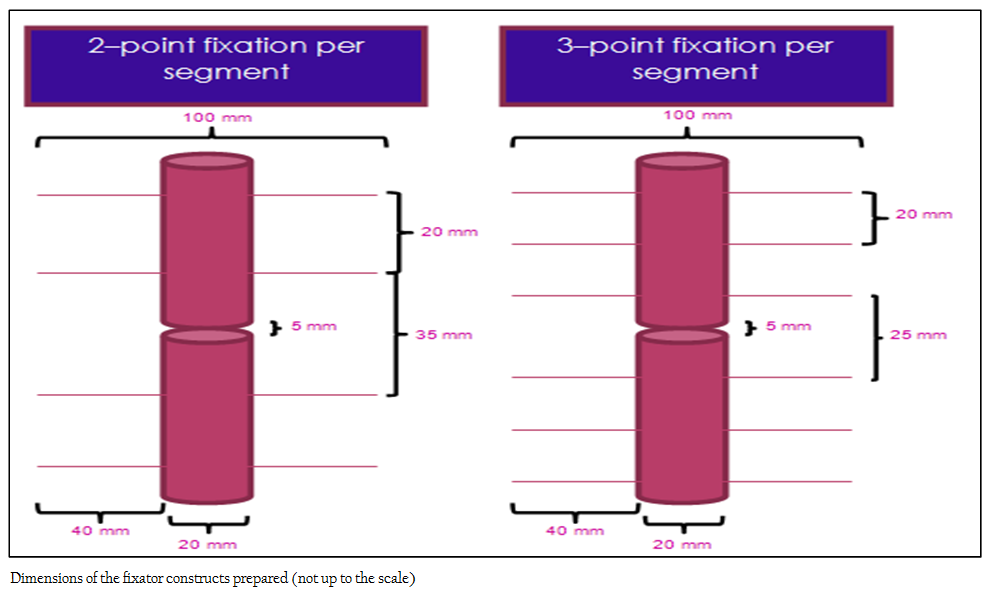
Two types of fixators were prepared; Group A (n=32) comprised of ESF with 2–point fixation per segment and Group B (n=32) comprised of ESF with 3–point fixation per segment (Figure 1). In group A, the nearer pins (closest to the gap) were passed at 1.5 cm distance from the gap. In both segments, the distance between the pins was kept 20 mm. In group B, nearer pin was passed at 10 mm distance from the gap. The distance between the pins in each segment was kept at 20 mm.
Pins were passed in the same line, parallel to each other, at fixed distance in uniplanar (U) design. Pins were crossed in multiplanar–I (M–I), multiplanar–II (M–II) and circular (C) designs at 90o angle taking care that the pins did not interfere with each other. A gap of 5 mm (to simulate an unstable fracture condition) was kept in between the two segments of UHDPE rods using a piece of plastic for temporary stabilization. The segments were then joined using removable adhesive tape, to keep the segments in proper alignment with respect to the planes of the pins passed. Side bars were constructed at uniform distance of 20 mm from the central UHDPE rod. Total length and diameter of the fixators were 145 mm and 100 mm, respectively, including the connecting bars.
Acrylic Fixators
PVC pipes of 20 mm diameter were connected to the pins in the same plane by piercing the pipes through and through the pin ends. The pipes were fixed at a constant distance (20 mm) from the rod. In multiplanar design–II (AM–II), the crossed pins on either side were connected at proximal and distal ends using additional pipes of appropriate length. In circular design (AC), the crossed pins were connected at all 4 points at proximal and distal ends by fixing the pipes in circular fashion to make rings. Side bars were made separately by connecting suitable length pipes. The side bars and rings were then joined by making openings in the rings and inserting side bars into it. The points of insertion were then secured with the help of adhesive tape. Thus temporary scaffolds of different fixator designs were prepared.
Self curing dental acrylic (Pyrax®–denture base polymer resin, Pyrax polymers–Roorke, India) was used in the present study. Acrylic powder (polymer) and liquid hardener (monomer) were mixed in a glass beaker immediately before application. Acrylic was poured into the side bars in semi liquid state. In design AC, a small opening was made at the proximal ring and then the semi–liquid acrylic was poured and allowed to flow down the whole scaffold. The open ends of side bars were sealed with the help of adhesive tape. Acrylic was then allowed to mix well between the side bars and rings (without forming cavities), polymerize and harden.
Epoxy Fixators
The pins in the same plane were bent towards the gap and joined with each other (using adhesive tape) to make a temporary scaffold. Additional pins were used for making frames of multiplanar designs (EM–I and EM–II) and circular design (EC). In design EM–II, the pins were joined proximally and distally between the side bars of same plane, so that 2 rectangles were formed on opposite sides. In circular construct, additional pins were used to make 2 rings, one at the proximal and one at the distal end.
The epoxy–resin (M–Seal® Phataphat, Pidilite Industries Ltd., Daman, India) was mixed thoroughly with the hardener for 1–2 minutes, till a uniform colour was achieved. The side bars of the fixator were then constructed by molding the epoxy on the pins by incorporating the bent pins within. The diameter of the epoxy column was kept uniform at 20 mm throughout. Subsequently, the epoxy was allowed to harden.
Mechanical Test
The fixator constructs were mounted on Servohydraulic Universal Testing Machine (UTM) and axial load was applied @ 3 mm/min. until failure. The load–deflection graphs were plotted. The maximum force at which failure of the fixator construct occurred was recorded and the stress, strain, modulus of elasticity and stiffness of fixator constructs were calculated (Rajput, 2006) as described below.
1. Stress = Load (Newton)/Area (mm2)
2. Strain = Change in Length (mm) / Initial Length
3. Stiff = Load (Newton) / Change in Length (mm)
4. Modulus of Elasticity = Stress / Strain
Statistical Analysis
Data obtained were analyzed using ANOVA, and mean differences were tested for statistical significance by Duncan’s Multiple Range Test (Snedecor and Cochran, 1994) using a software (Statistical Package for Social Sciences version 15.0). Significance was recorded at P < 0.05 and P < 0.01.
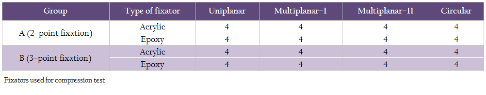
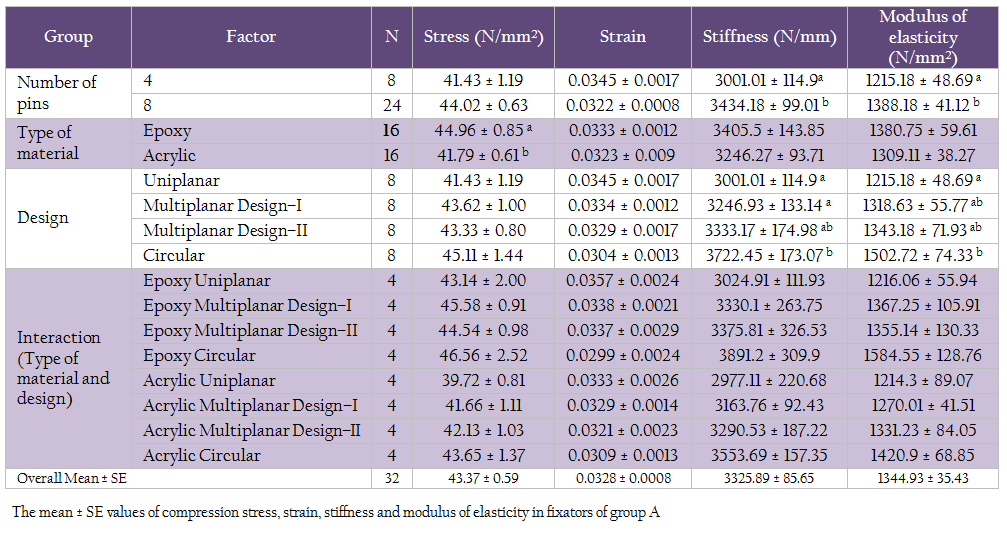
Table 2: The mean ± SE values of compression stress, strain, stiffness and modulus of elasticity in fixators of group A
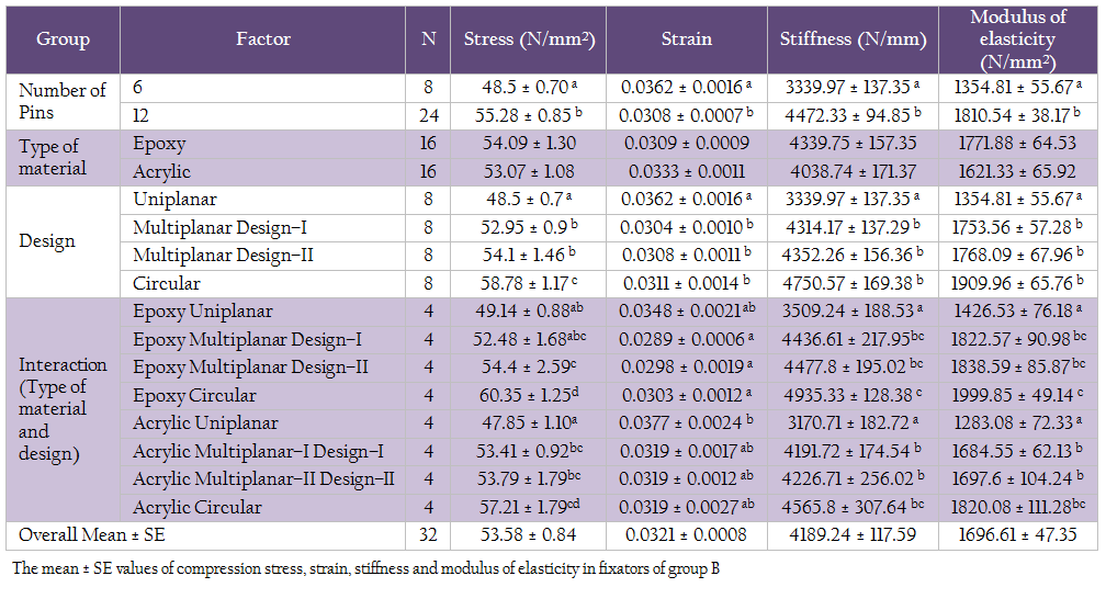
Table 3: The mean ± SE values of compression stress, strain, stiffness and modulus of elasticity in fixators of group B
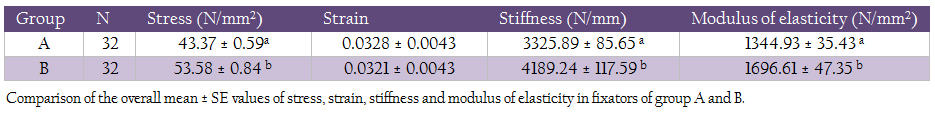
Table 4: Comparison of the overall mean ± SE values of stress, strain, stiffness and modulus of elasticity in fixators of group A and B.
RESULTS
Two–Point Fixation Constructs
The mean±SE values of stress, strain, stiffness and modulus of elasticity for fixator constructs of group A are given in table 2. On the basis of total number of pins used, it was divided as constructs with 4 pins and 8 pins. No significant (P>0.05) difference was recorded in stress and strain values of ESF constructs having 8 or 4 pins. The mean±SE values of stiffness and modulus of elasticity were significantly (P < 0.05) higher for ESF constructs having 8 pins (designs M–I, M–II and C) than for pins 4 (design U).
A significantly (P < 0.05) higher value of stress was recorded for epoxy constructs than acrylic constructs. However, no significant (P>0.05) difference was recorded in strain, stiffness and modulus of elasticity values between acrylic and epoxy fixator constructs.
There was no significant (P>0.05) difference in the stress and strain values between different designs of fixators as well. Stiffness of design C was non–significantly (P>0.05) higher than for design M–II, whereas stiffness values for designs C and M–II were significantly (P < 0.05) higher than for designs U and M–I. Modulus of elasticity of uniplanar fixator was significantly (P < 0.05) lower than other three designs; however, no significant (P > 0.05) difference was recorded between multiplanar (M–I and M–II) and circular (C) designs There was no significant (P > 0.05) difference in stress, strain, stiffness and modulus of elasticity between acrylic and epoxy fixators for a particular design i.e., no interaction was observed.
Three–Point Fixation Constructs
The mean±SE values of stress, strain, stiffness and modulus of elasticity for group B constructs are shown in table 3. On the basis of total number of pins used, they were divided as fixators with 6 pins and fixators with 12 pins. The average stress, stiffness and modulus of elasticity for fixator constructs with 12 pins (multiplanar/circular) was significantly (P < 0.01) more than for 6 pin constructs (uniplanar).
No significant (P > 0.05) difference was recorded in the values of stress, strain, stiffness and modulus of elasticity between the acrylic and epoxy fixators.
A significant (P < 0.01) difference in mean±SE value of stress was recorded; design C having the highest value, followed by designs M–II and M–I, whereas design U had the lowest value. Among the different designs, a significantly (P < 0.05) higher value of strain was recorded in uniplanar design than the other three. There was a non–significant (P > 0.05) difference in stiffness and modulus of elasticity values between the C and M–I and M–II designs; whereas, the value for design U was significantly (P < 0.01) lower than others.
The mean±SE value of stress for epoxy circular fixator was non–significantly (P > 0.05) higher than for acrylic circular fixator; however, it was significantly (P < 0.01) higher than the values for other fixator designs. The value for AC design was non–significantly (P > 0.05) higher than AM–I and AM–II and EM–I and EM–II designs. The mean±SE value of stress for design AU was the lowest.
Among the different designs of acrylic and epoxy fixators, a significantly (P < 0.05) higher value of strain was recorded in acrylic and epoxy uniplanar designs (AU and EU). Further, in acrylic group the values of strain were non–significantly (P > 0.05) different among the 4 designs. Similarly, among the epoxy group the values of strain were non–significantly (P > 0.05) different among the 4 designs. However, acrylic and epoxy constructs differed significantly with higher strain generated in acrylic constructs.
The mean±SE values of stiffness and modulus of elasticity for EC, AC, EM–I, EM–II designs were significantly (P < 0.05) higher than for other designs. There was no significant (P > 0.05) difference between multiplanar designs of epoxy or acrylic fixators. The values of stiffness and modulus of elasticity for uniplanar designs of both epoxy and acrylic fixators were significantly (P < 0.05) lower than for all other designs.
Comparison between 2–Point Fixation Constructs and 3–Point Fixation Constructs
The mean±SE values of stress (N/mm2), strain, stiffness (N/mm) and modulus of elasticity (N/mm2) for fixators of groups A and B are given in table 4. A significantly (P < 0.01) higher value of stress, stiffness and modulus of elasticity were recorded in the ESF constructs with 3–point fixation per segment than in 2–point fixation per segment, showing that the fixator constructs with 3–point fixation per segment are stronger.
DISCUSSION
Compression is an important force in the fracture biomechanics, which acts in axial direction (Calhoun et al., 1992). When it is applied on a structure it tends to shorten and widen it with maximal stress on a plane perpendicular to the load applied. The tendency to deform when a load applied is resisted by the internal resilience of the material, and it is said to be in a state of stress; and the strain is the deformation of the material relative to the stress (Gupta, 2009). According to the Hook’s law, the ratio of unit stress to the unit strain is the modulus of elasticity and is often called Young’s modulus (Rajput, 2006).
To minimize the variation due to size, age, breed, sex and condition of the animal, plastic rods of uniform diameter were used in this mechanical study. 19 mm thick Delerin rods have been used in biomechanical testing of ESF constructs by Lewis et al., (2001) and White et al., (2003). Solid Acetal rods of 22 mm diameter and 25 cm length were used by Alan et al., (2004). In the present study, UHDPE pipes of 20 mm diameter were used to form ESF constructs. Shahar (2000) suggested a minimum diameter of 19.1 mm if acrylic column is used as a substitute of connecting bar of Kirschner apparatus for animals weighing 12–45 kg. The diameter of side bars of both acrylic and epoxy–pin fixators was kept 20 mm for all the designs in the present study. The diameter and length of pins used were also kept constant. For external fixation of fractured bones in dogs and cats, 1–1.6 mm K–wires have been used (Ferriti, 1991; Kumar et al., 2012). The angle between opposing pins was kept close to 90o to maximize stability and minimize shear (Paley, 1991). A variety of acrylics (medical grade) is available in the market, dental and bone cement acrylic being the commonly available. Dental acrylic is relatively easily available and more economical, so was used in the present study. A number of epoxy putty (industrial grade) is available in the market. Because of the easy availability of M–seal® (Pidilite Industries Ltd., Daman, India) in the market and better handling characters, it was selected in this study. When the load was applied, 3–pin support per segment constructs was found to be significantly stronger than 2–pin per segment constructs. The fixators with 3–support points were nearly 1.26 times stronger than those with 2–support points. The higher stiffness and modulus of the 3–pin support design may be due to more number of pins spanning the greater length of the segment (Anderson and St. Jean, 1996).
Number of fixation pins in the proximal and distal major bone fragments also influences the fixator stiffness and affects the distribution of the physiologic loads among pins. Increasing the number of pins distributes the force among the pins and increases the stiffness of the overall construct (David and Nirmal, 2007). The greater the number of fixation pins per fragment, the more effective is the device in stabilizing the fracture and maintain pin–bone interface integrity (Palmer et al., 1991; Bouvy et al., 1993). In the present study, in 2–point support designs, the 8 pin (multiplanar/circular) constructs were 1.14 times stiffer than 4 pin constructs (uniplanar). A more marked difference was seen with 3–point support designs in which a 1.34 times increase was observed with 12 pin (multiplanar) constructs than 6 pin constructs (uniplanar). These findings further prove that by using more number of pins and inserting pins in different planes, the stiffness and strength to the fixator constructs can be increased appreciably.
There was a marked increase in the strength of the constructs with the increase in the complexity of designs. The uniplanar design was significantly weaker in axial compression than the other three designs. The circular design was able to bear significantly more stress in axial compression than the others. Similar findings have been reported in earlier studies where the stiffness of the fixator increased with the increase in complexity of fixator designs (Johnson and DeCamp, 1999; White et al., 2003). Among the fixator constructs with 2–support points, designs C, M–II and M–I were 1.24, 1.11 and 1.08 times, respectively, stiffer than design U. A similar pattern was seen in 3–point support design constructs, but the increase in stiffness was more noticeable; design C was 1.42 times stiffer than design U, and designs M–I and M–II were about 1.30 times stiffer than design U. Similar findings have been reported in earlier studies where the stiffness of the fixator increased with the complexity of design of fixators (Johnson and DeCamp, 1999; White et al., 2003). However, in this study no significant difference was observed between the materials used for ESF construction i.e., acrylic or epoxy fixators, of similar design.
CONCLUSIONS
The results of this study indicate that multiplanar and circular designs are stronger in terms of stress bearing, stiffness and modulus under axial compression loading. Both acrylic and epoxy ESF constructs provide adequate strength to the fixation with no significant difference between them. It can be concluded that under compressive load, the number of pins and the planes in which the pins passed are the major factors contributing to the fixation stability of free–form ESF constructs, without any significant difference between the acrylic and epoxy putty used for the construction of ESF.
REFERENCES
Aithal HP, Amarpal, Kinjavdekar P, Pawde AM, Singh GR, Hoque M, Maiti SK, Setia HC (2007). Management of fractures near carpal joint of two calves by transarticular fixation with a circular external fixator. Vet. Rec. 161: 193 – 198.
http://dx.doi.org/10.1136/vr.161.6.193
PMid:17693629
Aithal HP, Amarpal, Kinjavdekar P, Pawde AM, Singh GR, Setia HC (2010a). Management of tibial fractures using a circular external fixator in two calves. Vet. Surg. 39: 621 – 626.
http://dx.doi.org/10.1111/j.1532-950X.2009.00643.x
PMid:20636557
Aithal HP, Kinjavdekar P, Amarpal, Pawde AM, Pratap K, Zama MMS, Surbhi, Monsang SW, Setia SC (2010b). Epoxy–pin external skeletal fixation for management of open long bone fractures in calves and foals. A review of 16 cases. Presented in 34th Annual Congress of Indian Society for Veterinary Surgery, Veterinary College, Puducherry, India, 8 – 10 Dec. 2010
Alan RC, Daniel DL, Steve R, Andrew JR (2004). Effect of various distal ringblock configurations on the biomechanical properties of circular external skeletal fixators for use in dogs and cats. Am. J. Vet. Res. 65: 393 – 398.
http://dx.doi.org/10.2460/ajvr.2004.65.393
Anderson DE, St Jean G (1996). External skeletal fixation in ruminants. Vet. Clin. North Am. Food Anim. Pract. 12: 117 – 152.
PMid:8705797
Bennet RA, Kuzma AB (1992). Fracture management in birds. J. Zoo Wildlife Med. 22: 5 – 38.
Bouvy BM, Markel MD, Chelikani S, Egger EL, Piermattei DL, Venderby R (1993). Ex vivo biomechanics of Kirschner–Ehmer external skeletal fixation applied to canine tibiae. Vet. Surg. 22: 194 – 207.
http://dx.doi.org/10.1111/j.1532-950X.1993.tb00382.x
PMid:8362502
Caulhon JH, Li F, Ledbetter BR, Gill CA (1992). Biomechanics of the Ilizarov fixator for fracture fixation. Clin. Orthopaed. 280: 15 – 22.
David PM, Nirmal CT (2007). Biomechanics of external fixation, a review of the literature. Bull. NYU Hosp. Joint Dis. 65: 294 – 299.
Ferretti A (1991). The application of the llizarov technique to vet med. In: Operative Principles of Ilizarov, Branchi–Maiocchi A, Aronson J (Eds). Medi Surgical Video, Milan, Italy. pp 551 – 570.
Gupta SK (2009). Properties of bulk matter. In: Modern's ABC of Physics, 15th edn., Gupta and Gupta (Eds.). Modern Publishers, India. pp 647 – 849.
http://dx.doi.org/10.1016/j.materresbull.2008.04.020
Johnson AL, DeCamp CE (1999). External skeletal fixation: linear fixators. Vet. Clin. North Am. Small Anim. Pract. 29: 1135 – 1143.
PMid:10503288
Kowalski M, Schemitsch EH, Harrington RM (1996). Comparative biomechanical evaluation of different external fixation sidebars: Stainless–steel tubes versus carbon fiber rods. J. Orthopaed. Trauma 10: 470 – 475.
http://dx.doi.org/10.1097/00005131-199610000-00004
PMid:8892146
Kumar P, Aithal HP, Kinjavdekar P, Amarpal, Pawde AM, Pratap K, Surbhi, Sinha DK (2012). Epoxy–pin external skeletal fixation for treatment of open fractures or dislocations in 36 dogs. Indian J. Vet. Surg. 33: 128 –132.
Lewis DD, Cross AR, Carmichael S, Anderson MA (2001). Recent advances in external skeletal fixation. J. Small Anim. Pract. 42: 103 – 112.
http://dx.doi.org/10.1111/j.1748-5827.2001.tb02006.x
PMid:11303852
Paley D (1991). Biomechanics of the llizarov external fixator. In: Operative Principles of Ilizarov. Bianchi–Maiocchi A, Aronson J (Eds). Medi. Surgical Video, Milan, Italy. pp 31 – 41.
Palmer RH, Hulse DH, Hyman WA, Palmer DR (1992). Principles of bone healing and biomechanics of external skeletal fixation. Vet. Clin. North Am. Small Anim. Pract. 22: 45 – 68.
PMid:1539430
Palmer RH, Hulse DH, Pollo FE, Hyman WA, Palmer DR, Rastegar S, Longnecter MT (1991). Pin loosening in external skeletal fixation: the effect of pin design and implantation site in the canine tibia. Scientific Presentation Abstracts: American College of Veterinary Surgeons 26th Annual Meeting, October 1991. Vet. Surg. 20: 343.
Radasch RM (1999). Biomechanics of bone and fractures. Vet. Clin. North Am. Small Anim. Pract. 29: 1045–1080.
PMid:10503284
Rajput RK (2006). Strength of Materials, Mechanics of Solids, 3rd edn. S–Chand and Company, New Delhi, India.
Roe SC, Keo T (1997). Epoxy putty for free–form external skeletal fixators. Vet. Surg. 26: 472 – 477.
http://dx.doi.org/10.1111/j.1532-950X.1997.tb00519.x
PMid:9387211
Shahar R (2000). Relative stiffness and stress of type I and type II external fixators: Acrylic versus stainless–steel connecting bars–a theoretical approach. Vet. Surg. 29: 59 – 69.
http://dx.doi.org/10.1111/j.1532-950X.2000.00059.x
PMid:10653496
Singh GR, Aithal HP, Saxena RK, Kinjavdekar P, Amarpal, Hoque M, Maiti SK, Pawde AM and Joshi HC (2007). In–Vitro biomechanical properties of linear, circular and hybrid external skeletal fixation devices developed for use in large ruminants. Vet. Surg. 36: 80–87.
http://dx.doi.org/10.1111/j.1532-950X.2007.00239.x
PMid:17214825
Snedecor GW, Cochran WG (1994). Statistical Methods, 8th edn. Iowa State University Press, Ames, IA.
Stampley AR, Lawrence D (1993) Acrylic external fixation in the treatment of complex mandibular fractures. Canine Pract. 18: 15 – 19.
Tyagi SK, Aithal HP, Kinjavdekar P, Amarpal, Pawde AM, Srivastava T, Tyagi KP, Monsang SW (2014). Comparative evaluation of in vitro mechanical properties of different designs of epoxy–pin external skeletal fixation systems. Vet. Surg. 43: DOI:10.1111/j.1532–950X.2013.12128.x
White DT, Bronson DG, Welch RD (2003). A mechanical comparison of veterinary linear external skeletal fixation system. Vet. Surg. 32: 507 –514.
http://dx.doi.org/10.1111/j.1532-950X.2003.00507.x
PMid:14648528
Willer RL, Egger EL, Histand MB (1991) Comparison of stainless steel versus acrylic for the connecting bar of external fixators. J. Am. Anim. Hosp. Assoc. 27: 541 – 548.